Domo-i
Home Automation System
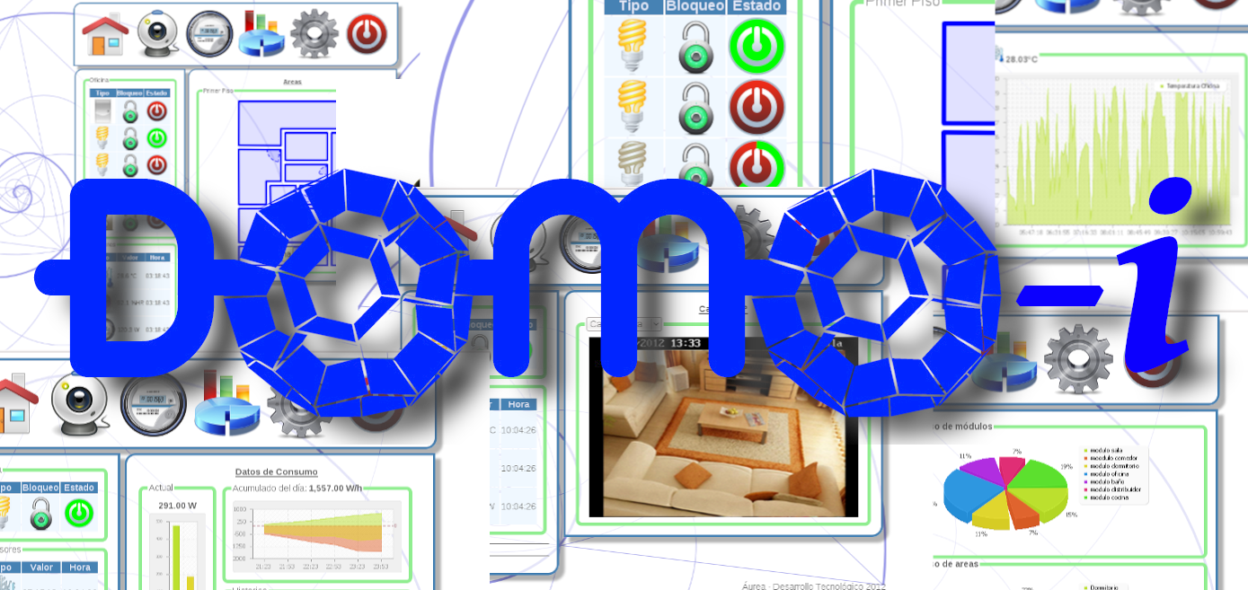
Este proyecto de Domótica fue un prototipo desarrollado antes de que los productos de domótica se volvieran ubicuos, tuvo un tiempo de desatollo de un año en el periodo 2011-2012 y aunque nunca vio la luz como un producto comercial o académico, nos enseño mucho sobre el desarrollo y fabricación u estándares de circuitos impresos y sistemas digitales.
Se desatollaron dos versiones para varios circuitos impresos de poder y control así como su respectivo firmware y software y una interface web para la interacción del usuario con el sistema.
Relay X6 v1
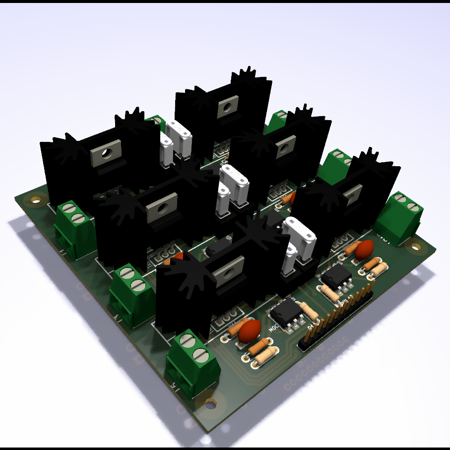
The first version of the power module consisted of six solid-state relays, opto-isolated from the control module, each with fuse and voltage spike protection.
Control V1
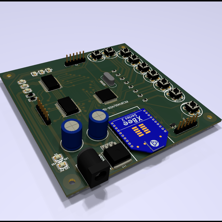
The first version of the control module consisted of a PIC18F4450 microcontroller, an XBee module and ten buttons, connected to the power module to control the six solid state relays. The modules were installed in an enclosure from which the wiring to the six loads and the voltage supply came out.
RFID card reader
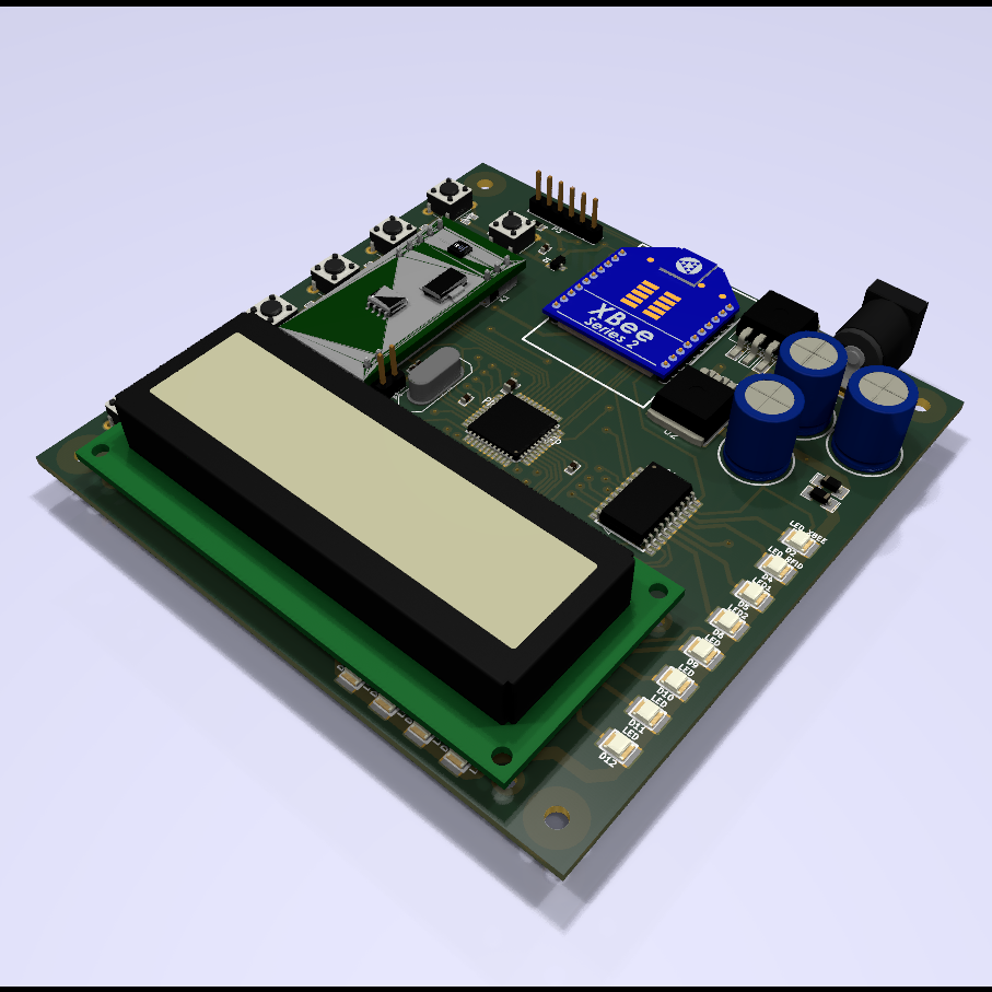
This module had: RFID card reading, LCD to interact with the user, six buttons, a PIC18F4450 microcontroller and an Xbee module. It allowed you to create access controls and control power modules remotely.
Xbee Gateway
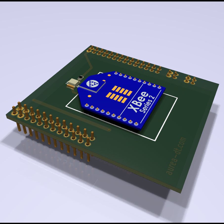
This module provides XBee wireless communication to the Linux server installed on a BeageBone card. The server allows the management of all wireless devices and the automation of events.
WallSwitch (Relay V2)
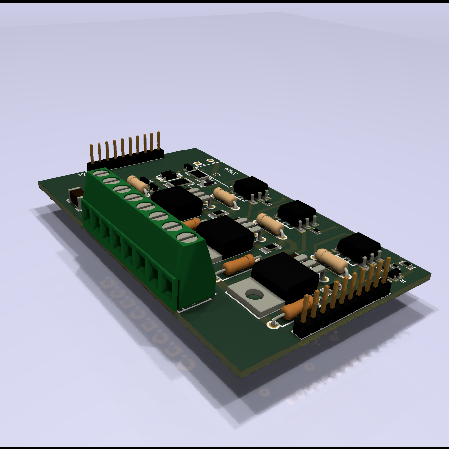
This printed circuit is the second version of the power module, this new version was designed in a very similar way to current wall switches. The complete module consists of three printed circuits: power, control and touch panel.
The power module consists of 3 opto-isolated solid state developers.
WallSwitch (Control V2)

This printed circuit is the second version of the control module, it is integrated with the control circuit and the touch panel to form the smart wall switch. It contains a PIC18F4450 microcontroller, a Zigbee module and USB connection.
Touch panel
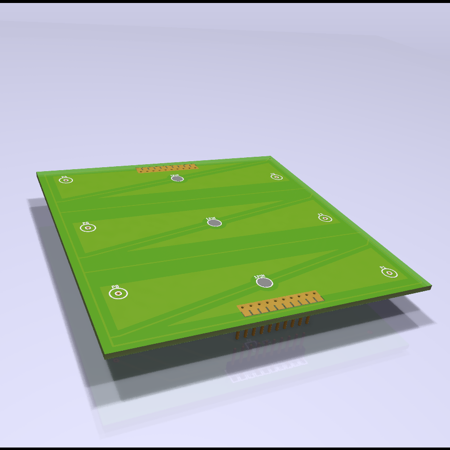
This touch panel connects with the control module and the power module to form the wallswitch, it contains three touch areas to control the solid state developers.
Touch panel floor plan
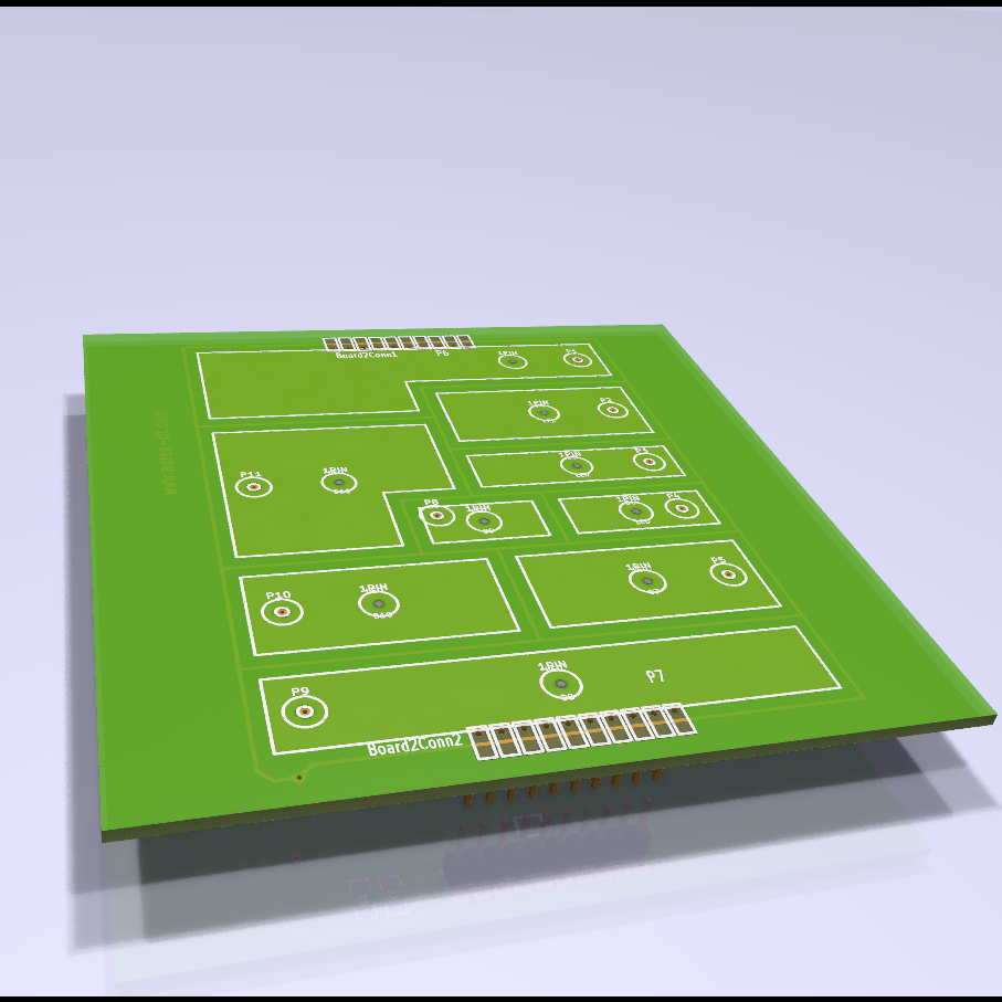
This touch panel shaped like the floor plan of the house where it was installed allows the user to control all the devices in an area at the same time.
MiWi Gateway
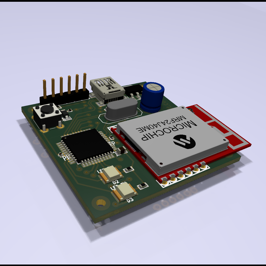
The second version of the gateway uses a Zigbee module and connects via USB to the Linux server.
Web App
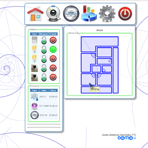
The user interacts with the home automation system through a web interface developed in PHP, where they can control the areas and devices, view sensors and schedule tasks.


